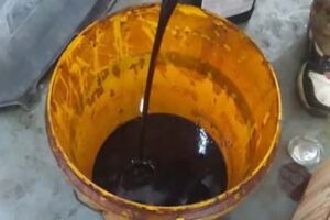
The oil yield is a factor that will dictate whether a particular pyrolysis setup will be effective and profitable. The higher the oil yield from waste materials, the higher the efficiency and profitability of the process. The higher the oil yield from waste materials, the lower the production cost for each unit of oil.
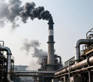
On the other hand, the flue gas is the result of the combustion of non-condensable gases and exhaust gases after heating. Flue gas consists of many types of pollutants such as particulate matter, acid gases, and volatile organic compounds. Pollutants in flue gases pose a problem since they have an adverse effect on people and the environment.
Oil yield and flue gas are important aspects in a pyrolysis setup. As much as high oil yield is essential in the process, it will result in more problems where the flue gas poses difficulties. The following sections of this paper explore major factors affecting oil yield and purification of flue gases.
The oil yields differ based on factors such as feedstock used, the design of the reactor, the temperature of the process, the heating rate of the waste, the time the waste spends in the reactor, and the seal of the reactor. These variables affect the oil yield, and a slight change in one of them can make a significant difference, up to 50% or higher.
Feedstock used. The nature of the waste used determines the amount of oil produced. For example, plastic wastes such as polyethylene and polypropylene produce a higher quantity of oil while rubber waste, mixed waste, and biomass produce lesser amounts of oil. Also, moisture content in the waste decreases the amount of oil produced. Wet waste yields less oil than dry waste.
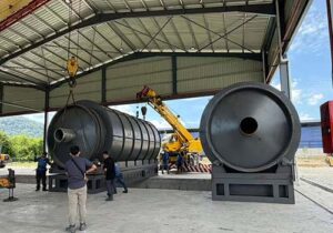
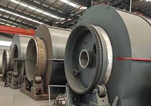
Reactor type. Rotating kiln, fixed bed, fluidized bed, and screw reactors all produce different yields. Some have higher consistency than others, and some produce a higher amount of char compared to others.
Temperature and Heating Rate. Temperature is the key parameter. Pyrolysis at low temperatures (350–450 ºС) normally results in heavy oils and char production. Pyrolysis at elevated temperatures (450–600 ºС) may lead to greater production of light oil and gases. Fast heating rate may facilitate liquid products generation due to the absence of secondary cracking. The slow heating rate may result in a greater quantity of char. It is up to your material which temperature would suit.
Residence Time. Residence time means the period of time the vapors and char stay in the hot zone. Short vapor residence time helps avoid secondary cracking, i.e., cracking of the vapor and resulting its conversion into gases. It helps increase the quantity of liquids produced.
Tightness of the System and Handling of Vapors. It will prevent air from getting into the pyrolysis chamber and ensure an inert atmosphere inside. Moreover, it will guarantee that all vapors go to the condenser.
Catalyst and additive. The effect of catalysts on reactions and production of oil is possible. The presence of catalysts will increase the share of gases and light oils if there is an acid reaction. Some types of catalysts can enhance oil qualities and decrease heavy fractions. They are quite expensive.
Feedstock preparation. It is necessary to shred, dry, eliminate metallic parts and stones from feedstocks in order to increase their quality and consequently improve oil yield and lower maintenance expenses.
Yield improvement is mostly a matter of input control process. Here are some measures that should be followed by the operators.
Use consistent input feed stock. In case of possibility, use one stream of materials. Get rid of all metals, stones, and inert fillers. Dry your feed stock to reduce water content.
Temperatures should be controlled. Use good quality thermocouples. Prevent temperature spikes. Choose proper temperatures depending on the analysis of your feed stock. In case of mixed plastics, temperatures from 400 to 500 °C will work fine. In case of tire, better results can be achieved using temperatures from 450 to 550 °C.
Change heating rate and vapor residence times. Higher heating rate and low residence time will result in higher yields of liquids. Make sure to optimize vapor paths for fast movement of vapor toward the condenser. There shouldn’t be any areas of high temperature because gases can break into lighter ones.
Improve condensation of gases. Use multistage condensation. Quick cooling of gas reduces second breaking.
Prevent air leakage. Conduct regular checks on seals and gaskets. Apply positive-pressure purging using nitrogen gas when necessary.
Use mild catalysts or absorbents only if you have evidence from the laboratory that supports their use. This should be conducted on a pilot scale. Note that the use of catalysts may cause poisoning of other units and make the handling process expensive.
Keep records. Document changes in feed properties, temperature distribution, processing speeds, and product yield. Changes could be indicative of fouling.
Conduct maintenance. Clean condensers, cyclones, and pipes regularly since fouling limits condensation and oil formation processes.
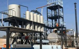
A comprehensive purification system will always consist of various types of purification technologies. In choosing which purification technology to implement, factors such as the nature of the fuel feed gas, emission standards, costs, and space availability will come into play. Here are some of the purification techniques that are widely used for gasification processes:
Cyclones/Demisters. These are among the initial defenses against contaminants in the gas. Cyclones employ the principle of centrifugation in order to separate particulates. Demisters separate oily droplets that can clog other pieces of downstream equipment. Cyclone/Demisters are easy to implement and use.
Quench/Condensation. This purification technique quickly lowers the temperature of the gas to minimize concentration. Quench Towers/Heat Exchangers remove oils and tars via condensation. Condensers are installed right after the reactor to remove oils and tars and prevent downstream wet scrubbers from being clogged.
Wet scrubbers. Acidic gases such as HCl, ammonia, H2S, and soluble VOCs are removed through wet scrubbers. This method works by bringing the gas in contact with a liquid phase. A packed bed and spray towers are used in this process to enhance gas-liquid interactions. Wet scrubbers can also be employed to eliminate fine particulate matter.
Injection of dry sorbent and bag filters. Dry sorbent injection involves the injection of alkaline substances like sodium bicarbonate and lime in the gas flow path to neutralize acids in it. The particulates are collected in a bag filter which acts as the baghouse downstream of the injection. The bag filters can be used for elimination of very fine particulates as well as solid products.
Activated carbon adsorption. Adsorption is performed using activated carbon to remove VOCs, dioxins, and odor compounds from exhaust gas. Activated carbon adsorbs the pollutants after the particulate control step is complete. Over time, the carbon gets saturated and needs to be either replaced or reactivated at high temperatures.
Thermal oxidation. In case of high concentrations of volatile and flammable VOCs or tar in exhaust gases, a thermal oxidizer (afterburner) is applied for oxidation of organics in high temperatures into carbon dioxide and water, thus reducing odor and VOC content. At the same time, a fuel source is needed for thermal oxidizer, and proper control of temperature and dwell time is required for NOₓ reduction.
Selective Catalytic Reduction (SCR) and Selective Non-Catalytic Reduction (SNCR). Both processes may be applied for NOₓ control. SNCR process consists of injection of ammonia or urea for NOₓ reduction. SCR process employs catalytic reaction for NOₓ reduction. On the other hand, it needs more pure gas and higher costs for construction.
Condensate and Wastewater Treatment. The wet scrubbing and quenching processes produce liquid effluent. Liquid effluent contains dissolved organics, acid, and particulates. Separation of oil and water, neutralization, and biological or chemical treatment is required for effluent treatment.
Stack and Final Polishing. After the cleaning processes, the gas may be run through a final polishing filter or bed, which may serve to polish the gas stream of any left-over impurities or odors. This is now prepared for discharge through the stack. The size of the stack will normally be defined according to local regulations.
Equipment design principles and sequence. Equipment train for pyrolysis flue gas typically includes the following units, in this particular order:
Cyclone/demister –> condenser/quench –> scrubbing or dry injection process –> baghouse –> activated carbon –> thermal oxidizer (if necessary) –> stack
The specific train depends on what is being done about certain pollutants. Design equipment so as not to damage sensitive units. A cyclone or similar unit should come before an activated carbon unit in order to avoid plugging up the bed too quickly.
Materials. Acid gases are frequently found in flue gases, requiring corrosion resistant materials. Some materials that are often used in scrubbers include stainless steel, lined steel and FRP (fiber reinforced plastics).
Bypass/Isolation and Redundancies. Bypass and isolation valves are essential in order to facilitate maintenance. Having redundant fans and pumps can save on downtime during maintenance.
Match Purification Needs with Feedstock
When you have a lot of plastic material, it means you have a lot of VOCs and tars. Hence, you should be more inclined towards condensers and carbon beds. With tire material, you have sulfur compounds and would hence like materials that will cope with the acidic gases.
Manage Between Capital Costs and Operating Costs
The highly efficient systems will require a high initial capital cost but will ensure you are saved from penalties, downtime, and maintenance. The less complicated systems will reduce capital costs but may result in increased operating costs.
Take into Consideration Feedstock Variability
In case your feedstocks are mixed, their composition will vary from time to time. It makes sense therefore to go for a system capable of handling different compositions of the feedstock. Controls that are flexible are a very useful consideration here. You also need sensors for rapid detection of emission changes.
Run Pilot Tests
Before scaling any system or material, it pays to conduct a pilot run.
Talk to Your Local Regulators
It always helps to talk to the regulators when making your decisions. Their ideas of an acceptable solution will vary depending on your location.